![]()
Manufactured in accordance with IS EN13155: 2003 + A2: 2009 - Cranes - Safety - Non Fixed Load Lifting Attachments.
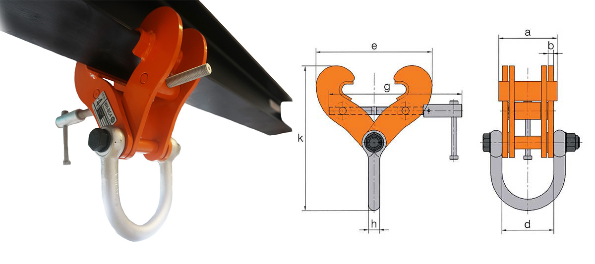
- The WH BC fixed jaw super clamp is fitted with a 'gussett' in both jaws maximising contact between the beam and clamp thus increasing the grip.
- A shackle is fitted to the bottom allowing an easy connection of the hoist to beattached.
- This fixed jaw super clamp can be used to an angle of 45° to the vertical.
- When the angle is moved away from the vertical the working load limit of the beam clamp needs to be reduced.
- Please refer to the table opposite - reduction in working load limits when side loads are applied.


| Part Code |
Model No. |
W.L.L. tonnes |
Beam Range mm |
Max Beam Thickness mm |
A mm |
B mm |
D mm |
E mm |
E mm |
G mm |
K mm |
K mm |
H mm |
Mass kgs |
|---|---|---|---|---|---|---|---|---|---|---|---|---|---|---|
| 027.200 | WH-BC2 | 2.0 | 76-190 | 20 | 130 | 3 | 90 | 254 | 133 | 275 | 263 | 223 | 20 | 4.0 |
| 027.320 | WH-BC3 | 3.2 | 76-190 | 28 | 130 | 12 | 102 | 275 | 166 | 275 | 289 | 251 | 20 | 8.0 |
| 027.320.E | WH-BC3W | 3.2 | 127-350 | 28 | 130 | 12 | 102 | 438 | 228 | 560 | 375 | 294 | 20 | 11.5 |
| 027.400 | WH-BC4 | 4.0 | 150-254 | 24 | 130 | 10 | 112 | 371 | 185 | 410 | 369 | 308 | 25 | 11.0 |
| 027.500 | WH-BC5 | 5.0 | 76-190 | 24 | 130 | 12 | 116 | 306 | 191 | 295 | 338 | 300 | 25 | 10.0 |
| 027.500.E | WH-BC5W | 5.0 | 150-305 | 24 | 130 | 12 | 116 | 422 | 264 | 410 | 413 | 360 | 25 | 15.0 |
| 027.600 | WH-BC6 | 6.0 | 203-457 | 36 | 140 | 12 | 116 | 608 | 267 | 560 | 511 | 402 | 25 | 18.8 |
| 027/1000 | WH-BC10 | 10.0 | 203-457 | 36 | 140 | 20 | 118 | 608 | 267 | 560 | 530 | 421 | 32 | 28.0 |
| 027/1500 | WH-BC15 | 15.0 | 203-457 | 66 | 170 | 20 | 116.5 | 648 | 400 | 660 | 684 | 608 | 40 | 49.5 |
| 027/1500.E | WH-BC15W | 15.0 | 406-610 | 66 | 170 | 20 | 116.5 | 800 | 600 | 810 | 812 | 706 | 40 | 58.5 |
Swipe horizontally on Specs Table to view all information.
![]()
| Angle from Vertical | 0° | 0° to 15° | 15° to 30° | 30° to 45° |
|---|---|---|---|---|
| Reduction Factor | Nil | 17% | 34% | 50% |
| Models | WLL | WLL | WLL | WLL |
| 027.200 | 2 tonne | N/A | N/A | N/A |
| 027.320,027.320.E | 3.2 tonne | 2.5 tonne | 2 tonne | 1.5 tonne |
| 027.400 | 4 tonne | 3.3 tonne | 2.6 tonne | 2 tonne |
| 027.500, 027.500.E | 5 tonne | 4.1 tonne | 3.3 tonne | 2.5 tonne |
| 027.600 | 6 tonne | 5 tonne | 4 tonne | 3 tonne |
| 027/1000 | 10 tonne | 8.3 tonne | 6.5 tonne | 5 tonne |
| 027/1500, 027/1500E | 15 tonne | 12.4 tonne | 10 tonne | 7.5 tonne |
Swipe horizontally on Specs Table to view all information.
- The above working load limits and derations have been established specifically for most William Hackett clamps and only apply in overhead beam attachment i.e: DO NOT apply if clamps are to be used for lifting beams.
- The tables apply to our clamps only (selected models) and we strongly advise that stress calculations should be carried out (by the user's engineering department) for all support steelwork.
WARNING: All clamps must be correctly applied to the beam by a competent person and fully hand tightened. If in doubt, contact the manufacturer for their recommendations.
NOTE: Clamp model WH BC (027.200) is not suitable for any side loading as it is of lightweight design.
- Although we are confident that our beam clamps could operate at 90° without any reduction in efficiency, William Hackett do not recommend this type of use in application, there will be a significant overturning moment generated on the beam flange and this could result in the actual supporting structure being permanently deformed and or damaged. If clamps are used in any other way than that indicated above, William Hackett will not accept any liability and would strongly recommend that this unsafe practice is not adopted.